Pressure profile
→ For graphical representation of the pressure curve
To calculate the pressure profile, the same conditions as for throughput and dosing time calculations must be fulfilled. This applies to all input data (geometry, material data and processing parameters). Additionally, the calculation position (only in PSI) must be defined, for which the pressure profile along the screw length is to be calculated. The same equations as those used in the throughput calculation are applied.
The pressure profile is calculated from the screw tip back to the location of the melt pool formation. Before this location, solid conveying takes place, which shows an exponential pressure build-up.
The pressure profile calculation begins at the screw tip. Based on the calculated throughput, the pressure drop within a computation interval is determined and added to the previous absolute pressure. In injection molding machines, the pressure in the screw antechamber (at the screw tip) results from the set back pressure.
Pressure Profile Calculation for Barrier and Wave Screws
Assumption of Equal Pressure Gradient
Barrier screws can only be calculated analytically under the simplifying assumption of an equal pressure gradient in the melt and solid channels. Although this allows for rapid calculation, the simplification reduces simulation accuracy.
Network Calculation / Matrix Model
To eliminate the above-mentioned simplifying assumption, the so-called matrix model was additionally implemented. Its calculation process is similar to the FEM method, generating a mesh within the flow domain. The Matrix Model is an analogy model based on network theory from electrical engineering.
This method is optionally available for barrier screws as an alternative to the equal pressure gradient assumption but is always used for wave screws.
A network is generated from the screw geometry, consisting of simple geometries (rectangular channels). For each of these simple geometries, a voltage source (drag flow) and a resistance (pressure flow) are defined. From the network of voltage sources and resistances, a matrix (linear system of equations) is generated and solved. Given a specified pressure drop in the zone, this allows determination of not only the throughput but also the pressure for each segment of the geometry, making the pressure profile across the section available.
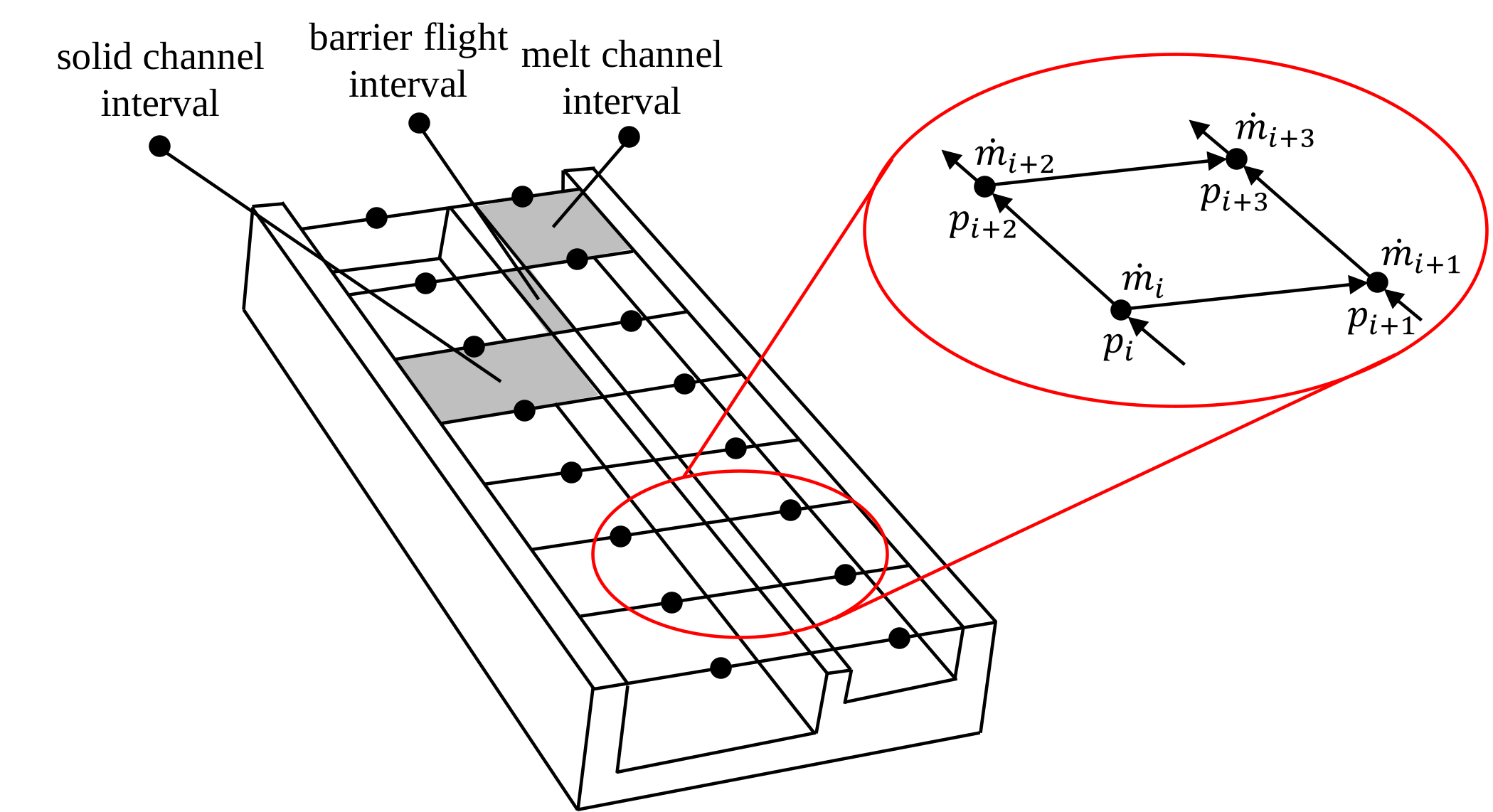
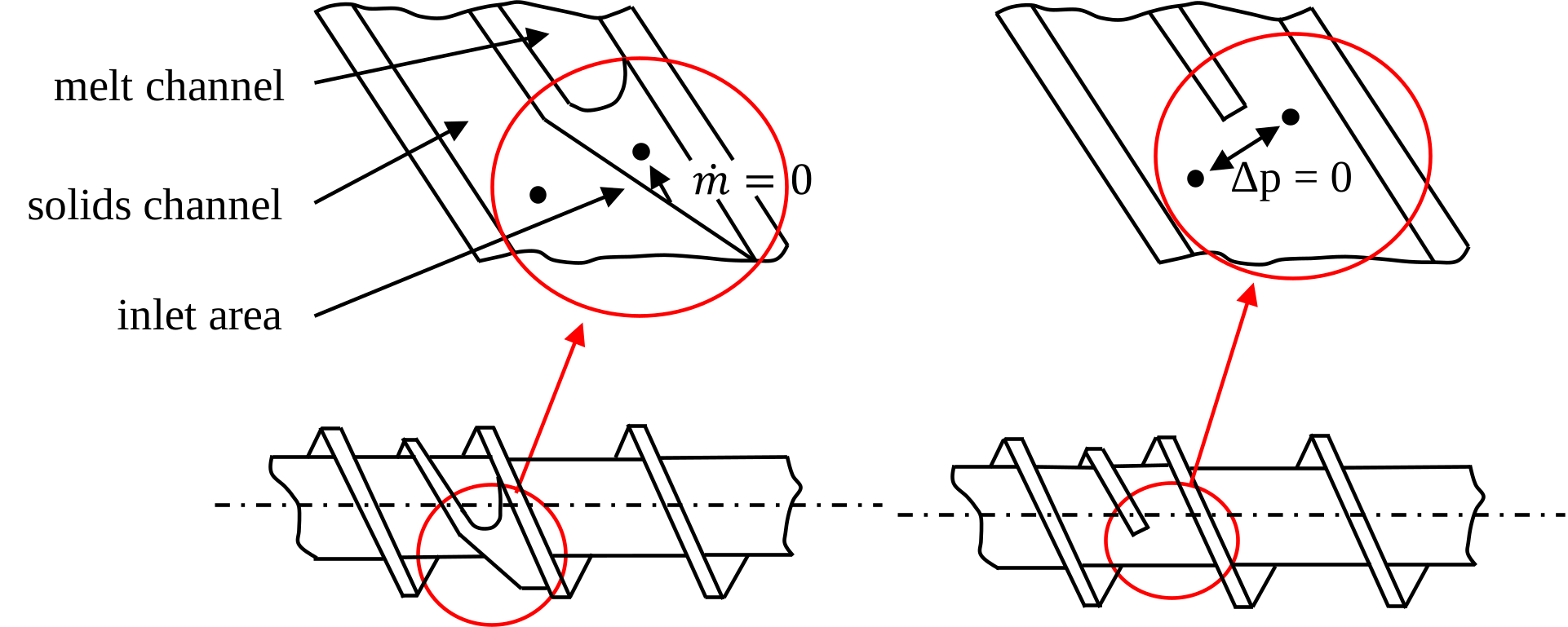
To solve the resulting system of equations, it must be reduced by incorporating boundary conditions. For a closed barrier zone, the mass flow into the closed inlet or out of the closed outlet can be set to zero. For an open barrier section and for wave screws, due to the lack of separation at the beginning and end of the section, the pressure difference between the channels is set to zero.