Inhaltsverzeichnis
Project explorer
The project explorer forms the left-hand side of the simulation environment in REX/PSI Next Generation and is divided into three main areas. It is used to manage and navigate projects, materials and machine configurations and provides a clear structure for accessing all relevant resources and data.
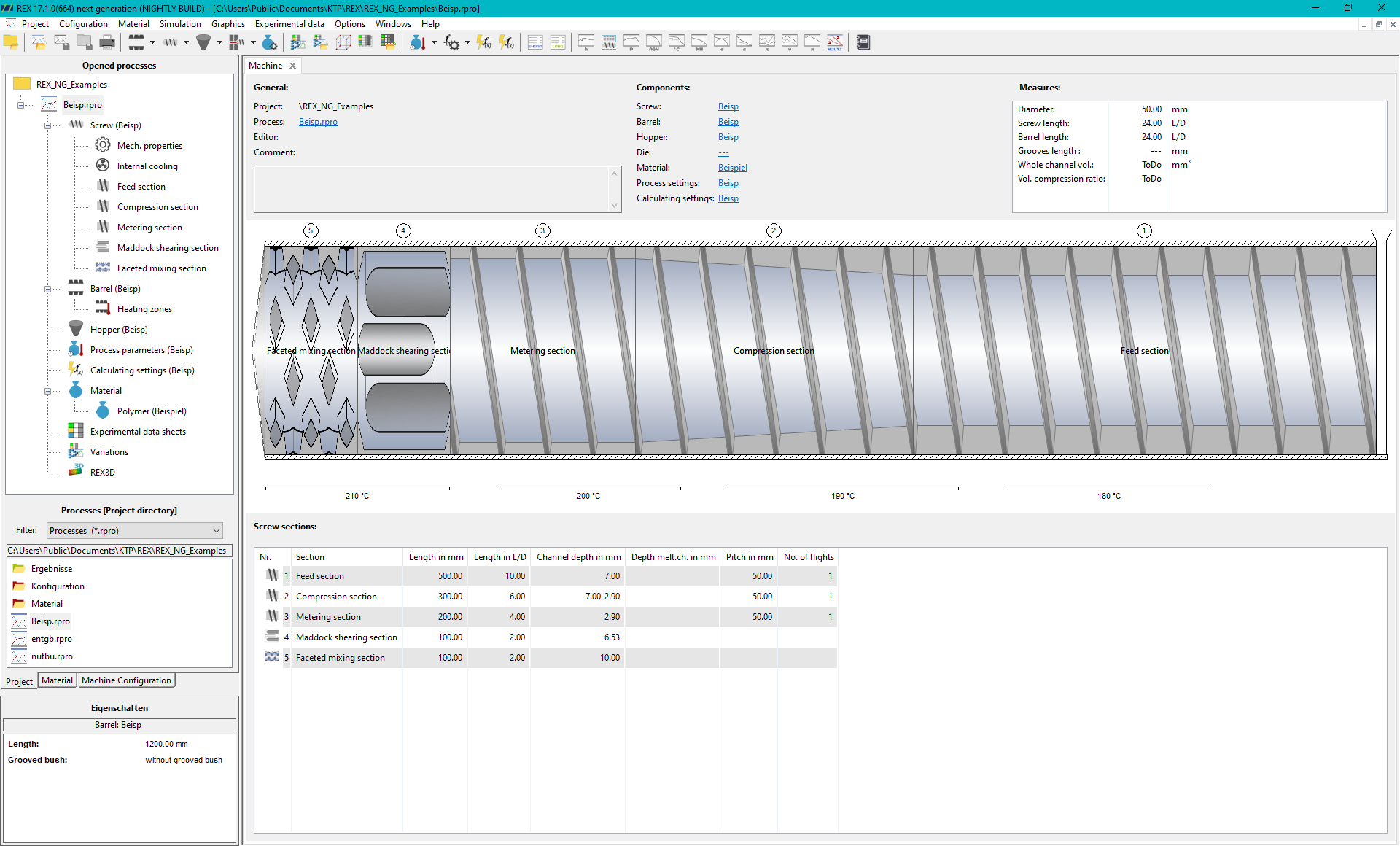
Upper area: Currently open processes and process directory
The currently open processes are displayed in the upper area of the project explorer. This allows the user to easily switch between different running simulations or projects.
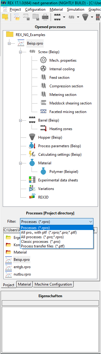
Middle Area: Process Explorer
Below this is the Process Explorer, which lists the currently selected project directory. All processes stored in the project directory can be displayed here and opened directly by double-clicking. The structure provides a quick overview of all processes that are available in the project.
Filter settings
In the filter settings, it is also possible to display and import older archives and processes:
- ptf archives: Old archives in PTF format can be easily integrated into the project structure.
- Pro import: Old process files in PRO format can also be imported and are therefore available in the current environment.
Materialexplorer
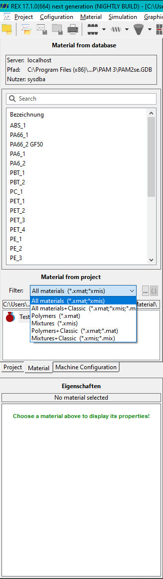
The second tab in the project explorer is the material explorer, which offers you two options for accessing material data:
- Connection to the PAM material database: You can use this option to connect to a PAM material database. This gives you access to all material data records that have previously been entered into the database. This enables centralised and consistent management of all material data within your projects.
- Local material folder: Alternatively, you have access to the local material folder, which contains materials in the new *.xmat- or *.xmis format. If old materials are still available in *.mat format, they can be opened with a double-click and automatically converted to the new REX/PSI Next Generation format. This conversion function makes it easier to transfer material data from earlier versions to the new simulation environment.
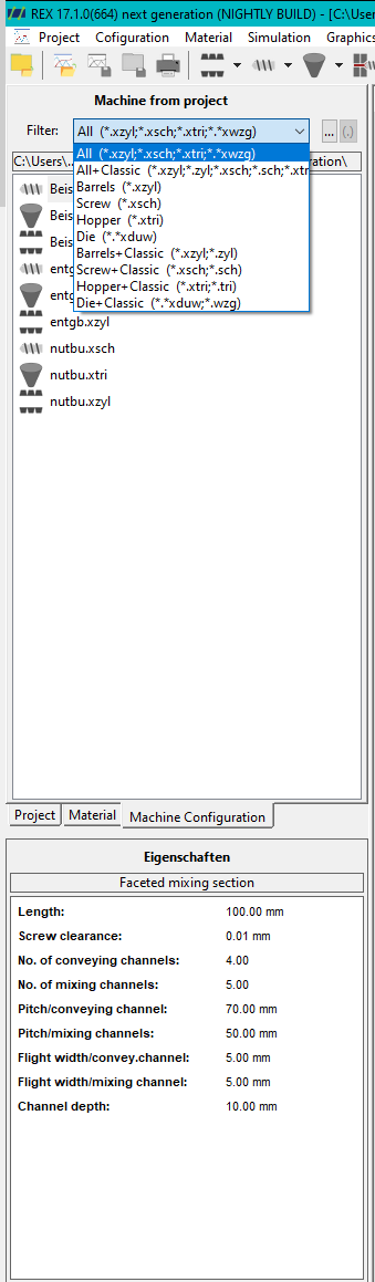
Machine configuration
The third tab in the Project Explorer is dedicated to variable machine configuration and displays all screws, hoppers, cylinders, and tool components within the configuration folder. The path for the components is defined in the general settings. By default, this path is located within the project directory.
The folder serves as an optional repository for all available machine elements, which can be viewed and modified via double-click in the Explorer. Machine elements can be added in two ways:
- Directly from the screw/cylinder/hopper/tool dialog via export into a file
- Via Project > Export Process > Seperate Files
The saved machine components can optionally be loaded and used either directly during process creation or through the corresponding dialog using Import from a file.
Bottom Area: Properties window
The properties window is located at the bottom of the project explorer. This window displays specific properties and parameters depending on the position of the mouse pointer in the user interface. For example, if the mouse pointer is positioned over a diagram, the corresponding result values are displayed. For machine components such as screws or cylinders, the geometry parameters are displayed in this area. This dynamic display of properties helps the user to quickly analyse and check process details or simulation results.