NRV - Annular non-return valve
Annular non-return valve
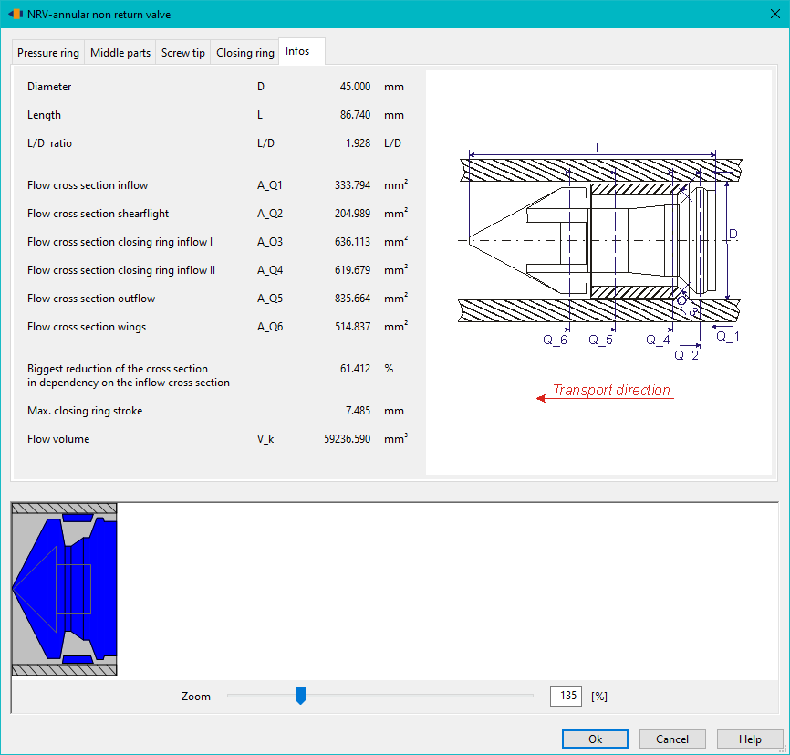
The ring non-return valve (NRV) is a screw component that is only available in PSI. In injection moulding screws, it prevents the molten material from flowing back into the screw during the injection process. The NRV has a three-part design. It consists of the pressure ring, the screw tip and the closing ring.
The ring non-return valve is generated with default values when the zone is inserted into the screw, in order to provide a dummy geometry without the need for manual input. The values can be changed afterwards as usual.
Function
The function of the NRV is basically as follows: During dosing, the material in the screw is conveyed towards the screw tip and melted in the process. The material flowing forwards presses the laterally movable closing ring against the screw tip. The material flows between the wings of the screw tip into the chamber in front of the screw. After dosing, the holding pressure phase starts. No further material is conveyed through the screw. The material flows back into the screw due to the pressure gradient. The clsoing ring is pushed back and hits the cone of the pressure ring. As this is not permeable in contrast to the screw tip, the closing ring and pressure ring close the screw and prevent further backflow.
When dosing starts again, the material conveyed forwards by the auger pushes the locking ring forwards again so that the auger chamber can be filled.
Structure
As mentioned above, the ring non-return valve is basically made up of three parts. In addition to the main components pressure ring, closing ring and screw tip, the middle part between the pressure ring and locking tip must also be defined in PSI.
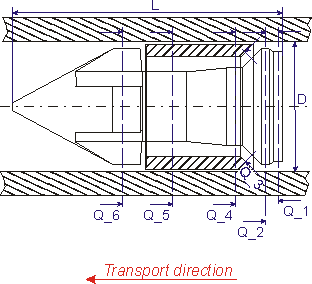
The NRV begins with the design of the pressure ring. Its task is to seal the screw against backflowing material in combination with the closing ring. For this purpose, it has a conical contact surface against which the closing ring presses.
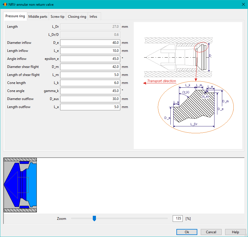
The design of this cone is of decisive importance for the functionality of the lock, as it forms the sealing surface for the clsoing ring. It is therefore possible to design it in detail in REX.
The middle parts are following to the pressure ring. Depending on the original geometry used, it is possible to assemble the middle parts from different individual geometries.
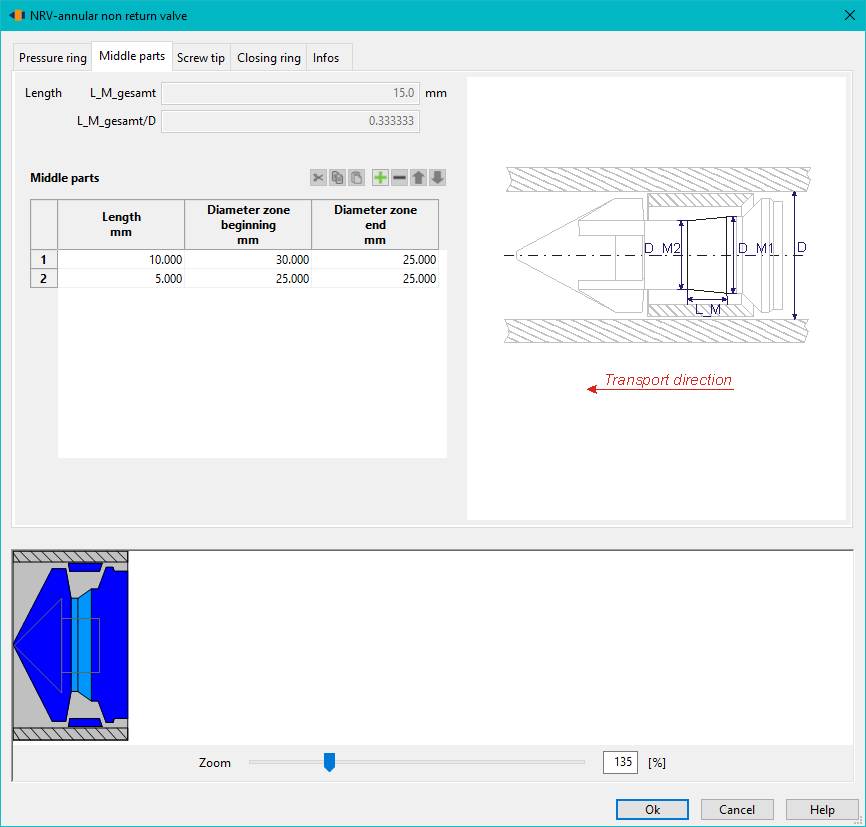
The middle part forms the connection between the pressure ring and the screw tip. Together with the closing ring, the middle part forms the flow channel for the melt and thus creates the decisive flow cross-section. If it is too large, the pressure on the closing ring is reduced so that it does not slide quickly enough into the closing position. If the flow cross-section is too small, the melt is severely impeded from flowing into the chamber in front of the screw.
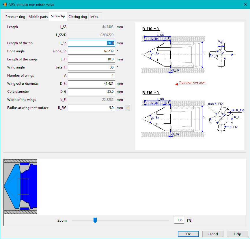
The middle part is then followed by the screw tip. It is designed as a wing tip. This allows the melt to flow through the tip during dosing when the locking ring is in the front position and into the screw antechamber. It should be designed to allow the melt to flow as freely as possible into the screw antechamber, avoiding dead zones. The rear side of the wings serves as a contact surface for the clsoing ring during dosing. They must be designed accordingly as a contact surface. This applies in particular to the wing angle $β_{Fl}$. This must correspond to the angle of the corresponding contact surface of the closing ring.
The number of wings is freely selectable. It should be selected in combination with the wing geometry so that the resulting flow cross-section is sufficient for the required melt throughput. As can be seen in the schematic diagram, the geometry is differentiated according to whether a $R_{Flg}$ is specified or not.
The last component is the closing ring. It is movably mounted to open the screw during dosing and to close the screw against backflowing material during injection.
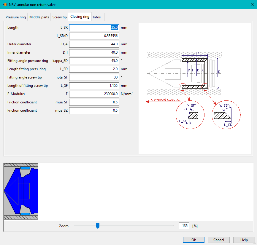
It initially rests against the screw tip or, when closing, against the pressure ring. The contact surfaces of the locking ring are therefore of decisive importance for the function of the NRV. It is important to ensure that the angles of the contact surfaces on both sides are selected so that the surfaces lie flat on top of each other. The outer diameter should be slightly smaller than the inner diameter of the cylinder: On the one hand, the lateral mobility of the ring must be guaranteed. On the other hand, the ring also performs a rotational movement: If it is pressed against the rotating screw tip during the dosing process, this takes the ring with it and forces it into a rotating movement.