Dies ist eine alte Version des Dokuments!
Melting profile
→ For a graphical representation of the melting process
The melting process is divided into three sections.
- First the location of the melt vortex formation (OSW) is calculated
- ‘Conventional’ melting begins from the location of the melt vortex formation
- From a certain switching point, conventional melting can change to disperse melting
The three sections are described below.
Calculation of melt vortex formation location
The location of the melt vortex formation describes the distance from the start of the channel to the position where the melt vortex forms. For calculating the melting length, it is assumed that the melt film between the barrel and the solid bed gradually increases. The required melt film thickness for the formation of the melt vortex corresponds to the average melt film thickness as determined by the conventional melting calculation. Due to the porous structure of the solid bed, the initial heat flux from the barrel is reduced. The lower the barrel temperature and the bulk density of the material in the channel, the further downstream the location of melt vortex formation will be.
Conventional melting
Conventional melting is carried out in REX according to the Maddock model for wall-adhering melts.
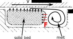
The solid bed is deposited on the non-driving (passive) flank of the screw channel. As the plastic melts, it is carried away to the active flank of the screw channel by the relative movement between the screw and barrel and by the ‘scraping’ by the screw flights. This creates a melt vortex, which simultaneously presses the solid bed against the non-driving flank.
As the melting process continues, the solids bed becomes narrower, but retains its height due to the pressure of the melt vortex. The solid bed width therefore decreases as a result of the melting process. If the channel geometry remains constant, the solids bed width decreases continuously. If the channel volume is reduced (lower channel depth, bigger flights, multi-flight section, lower channel pitch, restriction to the solid channel in barrier screws), the solids bed width increases, as the solids volume flow remains constant.
The dimensionless solids bed width $y$ shown in REX is normalised to the channel width: $y = \frac{solids bed width}{channel width}$
Clogging of the screw
Excessive compression of the screw channel can lead to plugging of the screw. If the blockage occurs outside a barrier or maillefer section, the melting calculation is aborted since no further melting progression can be determined. In such cases, it is recommended to use the calculation option “Currently under development: Iterate throughput in case of plugging”, which iteratively adjusts the throughput until a process state without plugging is achieved.
If the solid channel becomes blocked within a barrier or maillefer zone, the excess material is redirected into the melt channel. In the melt channel, a dispersed melting behavior is assumed. If both the solid and melt channels reach a solid bed width/solid content of $y>1$, the calculation is terminated. If the option “Currently under development: Iterate throughput in case of plugging” is selected, the throughput will be iteratively adjusted to a level at which the solid channel does not become plugged, thus preventing any solid material from entering the melt channel.
Degassing screws
If a degassing extruder is calculated, there are three options in the event that the plastic has not yet completely melted at the start of degassing (s. regular calculation):
- Melting up to degassing zone: The melting calculation is cancelled at the start of the degassing section
- Melting from degassing zone conventional: After the start of the degassing section, the melting process continues to be calculated using the conventional melting model.
- Melting from degassing zone dispersed: After the start of the degassing section, the melting process is calculated further using the dispersed melting model.
Special features in PSI
In addition to the plasticising phase, there are also downtimes in the injection moulding process during which the plastic continues to melt due to the cylinder temperature control. For consideration in REX, each interval is assigned a proportional downtime (the sum of all intervals corresponds to the specified downtime) and the melting is calculated within this downtime:
- $\text{Number of downtimes} = \frac{\text{Channel volume of the screw}}{\text{Dosing volume}}$
$\text{Total downtime}= \text{Number of downtimes} * \text{downtime}$
$\text{Normalised downtime} = \frac{\text{Total downtime}}{\text{Residence time}_{\text{Screw}}}$
$\text{downtime in interval}=\text{Residence time}_{\text{interval}}*\text{Normalised downtime}$
The proportional downtime per interval is used to take into account the melting due to the downtimes in the discontinuous injection moulding process. The equations for melting within the downtimes are taken from the following sources:
Sources
- Schulte, Hubertus: Grundlagen zur verfahrenstechnischen Auslegung von Spritzgießplastifiziereinheiten. Dissertation, Universität Paderborn, 1990
- Potente, Helmut: Simulation of Injection Molding and Comparison with Experimental Values. Intern. Polymer Processing VIII (1993) 3
Calculation of the melt fraction
The melt fraction is calculated from the current normalised solids bed width $y$, the current channel width $b$, channel height $h$, number of channels $i$, and the current solids bed velocity $v_{fz}$ in relation to the channel geometry at the location of the melt vortex formation and the solids bed velocity $v_{fz,OSW}$ present there
- $\text{melt fraction} = 1 - y * \frac{h*b*i*v_{fz}}{(h*b*i*v_{fz})_{OSW}}$
with
- $v_{fz,OSW} = \frac{\dot{V}}{(h*b*i)_{OSW}}$
and
- $ v_{fz,new} = v_{fz,old}*\left( \frac{h_{new}}{h_{old}}\right) ^a$
The factor $a$ (>0) describes the acceleration of the solid bed by reducing the channel height. If the channel height remains constant, the solid bed velocity remains constant; if the channel height decreases, the solid bed velocity increases; if the channel height increases, the solid bed velocity decreases.
Disperse melting
Disperse melting requires a sufficiently high melt content and means that the unmelted plastic is distributed in individual particles in the already melted plastic melt and melted by heat conduction from the plastic melt. The aim of disperse melting is to increase the melting capacity, improve thermal homogeneity and achieve a cooler plastic melt.
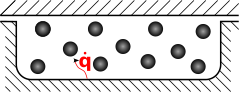
As can be seen in the illustration, the particles melt out of the molten plastic through heat conduction. This reduces the temperature of the plastic melt. At the same time, the high surface-to-volume ratio can lead to an increased melting rate. The melting rate depends on the particle size, the channel size, the solids content and the melt temperature. Depending on the influencing parameters, melting takes place faster or slower compared to the conventional melting model.
In addition to the cooling of the surrounding plastic melt, the solid particles also ensure an increased shear rate in the melt. Depending on the particle size and solid content, disperse melting can therefore either reduce or increase the temperature compared to the conventional melting model.
Sources
- Pape, Jens: Grundlagen der Prozesssimulation von Einschneckenkonzepten zur Hochleistungsplastifizierung, Dissertation, Universität Paderborn, 2006
- Dörner, Marius: Wave-Schnecken in der Einschneckenextrusion, Dissertation, Universität Paderborn, 2022