Dies ist eine alte Version des Dokuments!
Regular calculation
Starting a calculation
There are two ways to start the calculation
- With selection of the calculation and process settings
- Quick calculation with the last used calculation and process settings
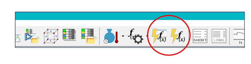
The first selection opens a window in which the process parameters and the calculation settings can be changed. The settings are presented below. Confirming the Calculate… button starts the calculation and the calculation progress and report display appears.
With the 2nd selection, the last known process and calculation settings are used and the progress and report display appears immediately.
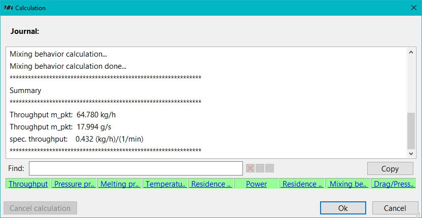
The calculation log appears in the upper part of the progress and report display. The calculation process can be recognised by the sequence at the bottom of the window.
Here means:
- Green: Successful calculation
- Orange: Warning message
- Red: Error message
By clicking on an orange or red field, the log jumps directly to the corresponding warning or error message.
Process parameters
Calculation settings
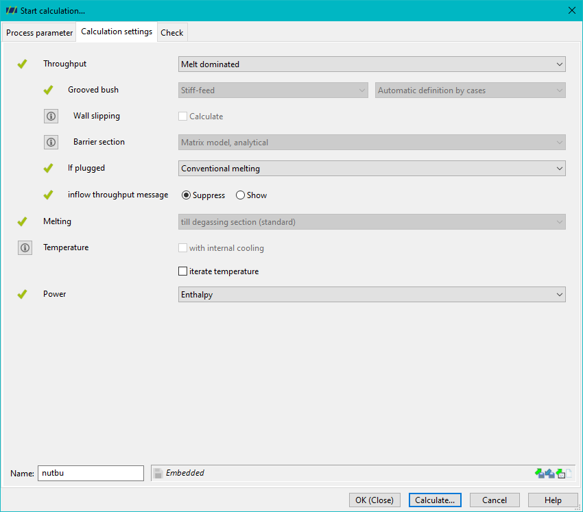
The calculation settings are divided into 4 sections:
1. Throughput
see also Throughput
Three basic settings are possible here
- Melt dominated: Standard setting, melt conveying dominates the throughput
- Coupling solids conveying: the Solids conveying of the feed zone is also taken into account
- Slot bushing: the throughput is determined by the Grooved bush (Grooved bush calculation).
If a grooved bush is defined, you can also select whether the calculation
- Stiff feed (default) or
- limited speed orientated
and the conveying case differentiation can also be selected.
You can also select whether the throughput calculation should take Wall-slipping into account. In this case, corresponding material data are required.
For screws with barrier zones, there are two options for calculating the pressure throughput
- The matrix model based on network theory, standard
- Assumption of a constant pressure gradient between the solids and melt channel
If a barrier zone becomes plugged (solids bed width y in the solids channel over 100% achieved by compressing the channel, within a barrier zone), the following options are available
- Continued conventional melting, in this case the the conventional melting continues in the solid channel. A disperse melting is assumed for the melt channel.
If solid bed widths of more than 100% outside a barrier section occur, the melting calculation is cancelled with a warning message.
It is also possible to select whether the message of an insufficient feed throughput through the hopper should be displayed or suppressed. It only makes sense to display the message if a hopper has been defined. Otherwise, a round hopper opening the size of the extruder's nominal diameter is assumed.
2. Melting
see also Melting
For degassing screws only, three options can be selected:
- till degassing section: Standard, the melting calculation stops at the first degassing section
- conventional melting after degassing section: conventional melting also in/after the degassing section. However, if disperse melting has already been forced, for example by a shearing part before the degassing section, disperse melting will continue to be calculated.
- disperse melting after the desgassing section: disperse melting in/after the degassing zone
3. Temperature
see also Temperature
- If Iterate temperature is not selected, the calculation is only calculated with an initial temperature profile. This is described by a linear progression of the temperature from the melting temperature ($T_G$ / $T_K$) at the front edge of the hopper to the specified final melt temperature (see necessary process parameters) at the screw tip. For degassing extruders, the specified final melt temperature already applies to the start of the first degassing zone and remains constant thereafter.
If Iteration of the final temperature is selected, the calculated temperature profile is used iteratively for a new calculation of the entire process until a stationary state (no change in the final temperature) is reached.
Since the influence of the entered melt temperature on the throughput is only minor, the temperature iteration can remain deactivated, provided a reasonable melt temperature can be estimated.
- If an internal temperature control is defined, the calculation of the internal temperature control can be activated or deactivated.
4. Power
Check
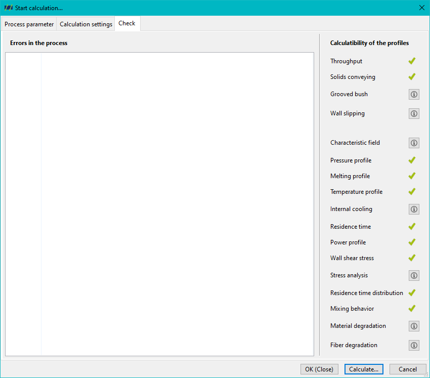
The Check overview summarises which curves and parameters can be calculated (green tick) or cannot be calculated (exclamation mark).
Click on the exclamation mark to display the reason why a curve or parameter cannot be calculated.