Dies ist eine alte Version des Dokuments!
Fiber length degradation
REX/PSI offers two calculation models for fibre degradation.
Simplified calculation approach ‘fibre length reduction’
→ For graphical representation of the fibre length reduction
The calculation takes into account the temporal regressive decrease in the average fibre length during shearing processes. This is described by the following equation:
$$\frac{dl}{dt_v}=-c \cdot l^2$$
with $$l = \frac{L-L_∞}{L_0-L_∞}, 0 < l ≤ 1$$
The solution of the Equation and the insertion of the boundary conditions produces the following descriptive equation:
$$l(t_V) = \frac{1}{\frac{t_V}{t_0}+1}$$
Where $t_0$ is the time constant at which a halving of the fiber length occurs. The time constant is determined by an energy-related view of the fiber breakage, taking into account the flow processes during plasticization. Energy is used to break a fiber. This energy causes buckling in line with Euler's second buckling case. Through the buckling process, the fiber breaks in the middle, thus halving the fiber length. The energy needed for the buckling can only be introduced into the process via the screw motion in the form of dissipation. Generally speaking, the dissipation energy generated in the process can be described as follows:
$$E_{diss} = η \cdot \dot γ^2 \cdot V \cdot t_V$$
Where $V$ is the melt volume of the area being studied, $η$ the viscosity of the plastic, $\dot γ$ the shear rate and $t_V$ the dwell time.
The given melt volume can be expressed for Euler's second buckling case as follows, assuming a linear elastic behavior:
$$E_{break} = V \cdot Φ \cdot \frac{E \cdot ε_B}{2}$$
By using the energetic equations the time constant $t_0$ is determined and used in equation 2. This results in the descriptive equation for the fiber length reduction, which is used in REX / PSI (Eq. 5).
$$l(t_V) = \frac{κ \cdot Φ \cdot E \cdot ε_B }{t_V \cdot ζ \cdot 2 \cdot η \cdot \dot γ^2 + κ \cdot Φ \cdot E \cdot ε_B}$$
Calculation modelling ‘Fibre length distribution’
Required properties of the reinforcing fibres or compound
- Tensile strength
- Elongation at break
- Modulus of elasticity
- Density
- Fibre weight fraction
Results of the fibre breakage calculation
- Number of weighted fibre lengths:
$$L_n = \frac{∑_in_i \cdot l_i}{∑_i n_i}$$
- Volume-weighted fibre length:
$$L_v = \frac{∑_i n_i \cdot {l_i}^2}{∑_i n_i \cdot l_i}$$
- Frequency distribution of fibre lengths: $l_i$
Procedure for calculating the fraction
When calculating the fibre length reduction in the plasticising process, a distinction is made between different zones and the damage mechanisms that occur there.
Calculation of fibre breakage at the solid bed - melt film interface
When processing short fibre-reinforced granulates, fibres are partially exposed from the granulate grain at the interface between the solid bed and the melt film. The melt flows around these fibres, which are anchored on one side, and can fail due to this stress. This failure does not occur with long fibre-reinforced materials. Due to the rod shape of the LGF granules and the high l/d ratio, vertically oriented fibres do not occur in the melt film.
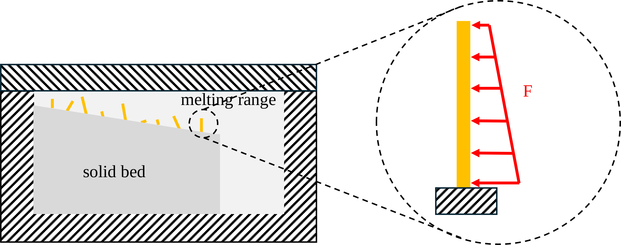
A fracture criterion is defined to check whether the fibres clamped at the interface break. This sets the bending stress exerted by the melt on the individual fibre in relation to the tensile strength of the fibre. If the bending stress of the fibre is higher than the tensile strength of the fibre, the fibre is assumed to have failed.
Breakage condition:
$$\frac{σ_{hydro}}{R_m} > 1$$
Calculation of fibre breakage in a melt flow
In addition to fibre breakage at the interface, damage occurs in the melt film and in the melt vortex to fibres that move freely in the melt. The fibre breakage that occurs here is calculated as follows:
It is fundamentally assumed that the failure occurs due to buckling of the fibres under compressive load. The fracture criterion thus results from the critical buckling force calculated according to the second Euler buckling case and the hydrodynamic force $F_i$ exerted by the melt on the fibre.
$$\frac{F_i}{F_{critical buckling force}} = \frac{8 \cdot ζ \cdot η_m \cdot {l_i}^4}{π^3 \cdot E_f \cdot {d_f}^4} (-D:A) > 1$$
$$F_i = \frac{ζ \cdot η_m \cdot {l_i}^2}{8}(-D:A)$$
$$F_{Buckling} = \frac{π^3 \cdot E_f \cdot {d_f}^4}{64 \cdot {l_i}^2}$$
$D$ = deformation tensor
$A$ = orientation tensor
$ζ$ = drag coefficient
The probability of breakage $P_i$ is defined depending on whether the breakage criterion is fulfilled. The fibre interaction coefficient $C_{FB}$ takes into account the influence of the fibre-fibre interaction or the fibre volume fraction on the fibre breakage. In addition to the fibre volume fraction, the fibre interaction coefficient is also dependent on the flow velocity in the channel and the fibre length.
$$ \mathrm{P_i} = \begin{cases} 0 & \text{für } \frac{F_i}{F_{crit}} \leq 1 \\ C_{FB,i}*\left( 1-exp\left( 1- \frac{F_i}{F_{Buckling}}\right) \right) & \text{für } \frac{F_i}{F_{crit}} > 1 \end{cases} $$
The break position of the fibre along the length $l_i$ is described with the assumption of a normal distribution and the definition of a break transition matrix.
$$R_{ji} = normpdf (l_j, \frac{l_i}{2}, Sl_i)$$
Finally, the transition matrix is normalised to the breakage probability.
$$∑_j R_{ji} = 2 P_i$$
The breakage model used here is based on Phelps' model from 2009 for calculating fibre breakage in the injection mould. However, the model was extended to include the fibre interaction coefficient by modifying the calculation of the probability of breakage.
Calculation of fibre breakage in a screw channel segment
For the various sections of the screw channel, the fibre breakage that occurs and the resulting fibre lengths in the individual sections are calculated and then added using volumetric weighting.
The following is an overview of the different variants that occur and which breakage calculations are taken into account.
Calculation of fibre breakage in the mixed solid bed + melt film
KGF: Breakage model for calculating fibre breakage at the interface + breakage model for melt flow in the melt film
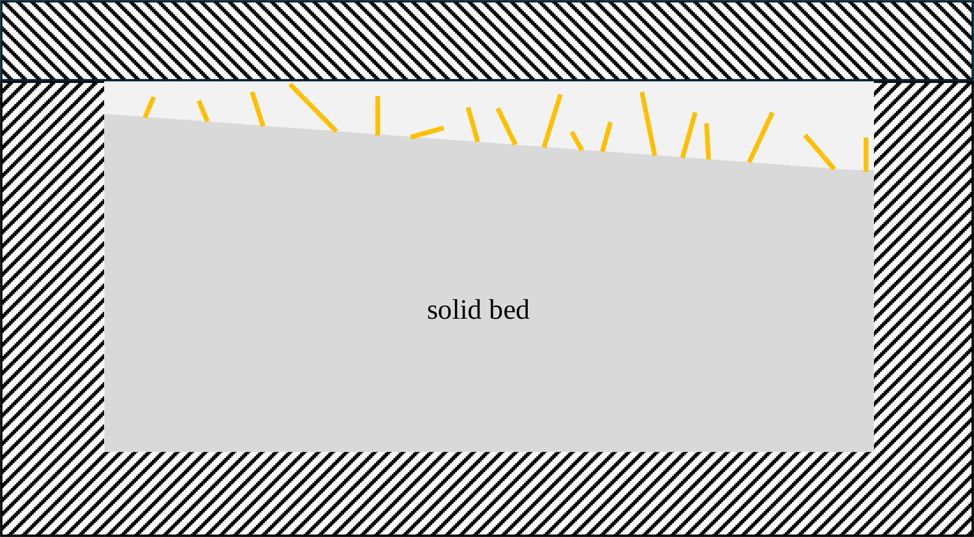
LFT: Fracture model for melt flow in the melt film

Calculation of fibre breakage in the mixed area of solid bed + melt film + melt vortex
KGF: Fracture model for calculating fibre breakage at the interface + fracture model for melt flow in the melt film + fracture model for melt flow in the melt vortex
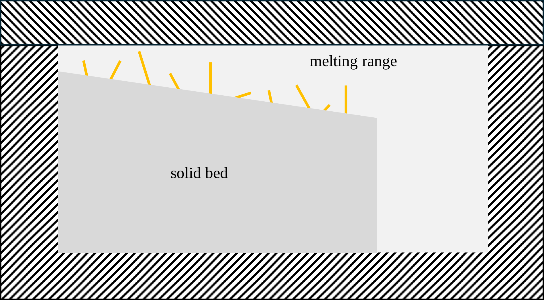
LFT: Fracture model for melt flow in the melt film + fracture model for melt flow in the melt vortex
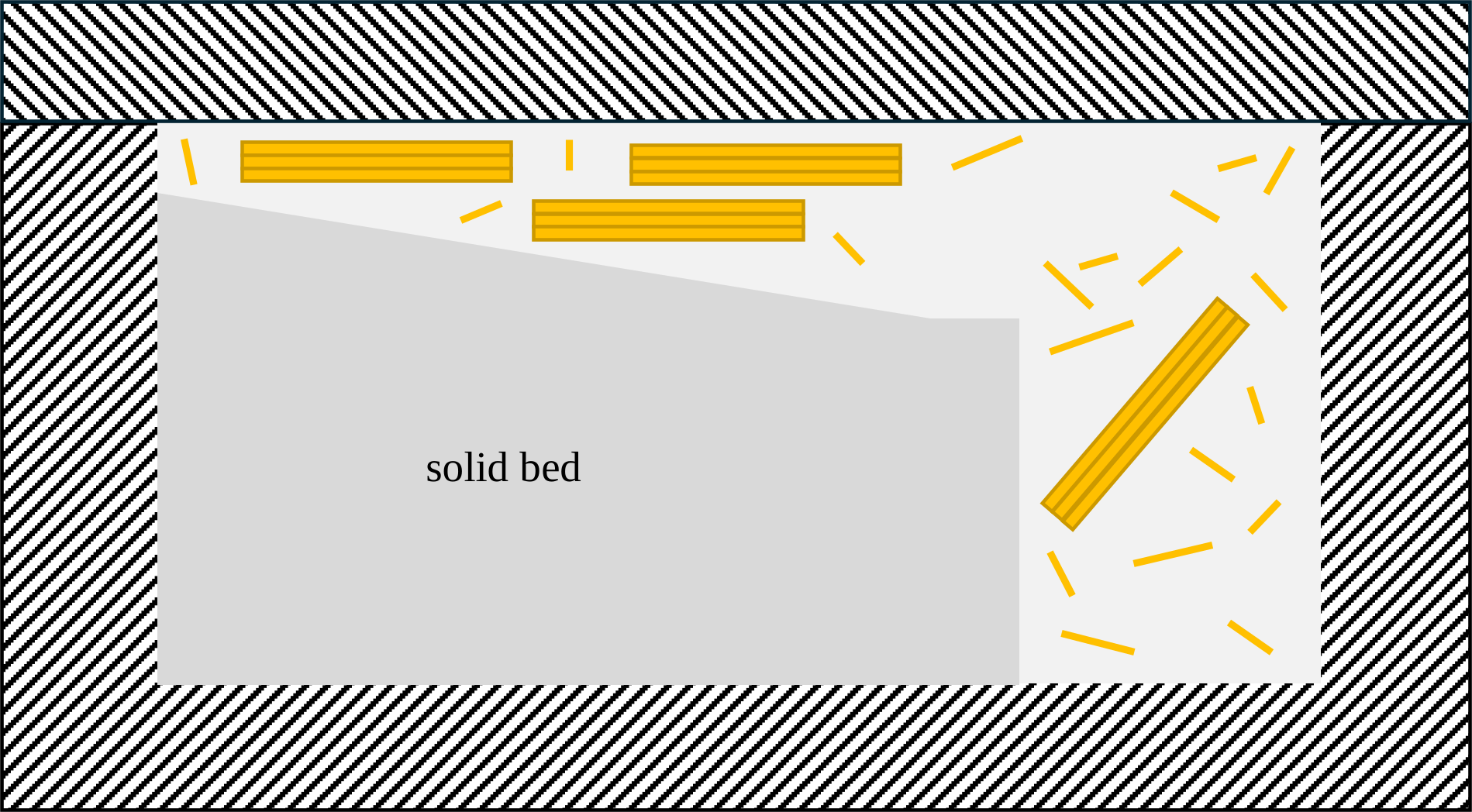
Fibre breakage calculation in the pure melt range
Fracture model for melt flow
