Dies ist eine alte Version des Dokuments!
Power and wall shear stress
→ For a graphical representation of the performance curve
Three models can be selected for power calculation in REX/PSI:
- Isothermal performance model
- Non-isothermal performance model (recommended model for melt extruders)
- Enthalpy model (recommended model for plasticising extruders)
All models are based on the results of the throughput, melting and temperature calculations. The enthalpy model also requires the pressure curve.
The accuracy of the power calculation therefore depends on the other curves. If experimental values are already known (e.g. flow rate), it is advisable to specify these for the power calculation.
For an accurate power calculation, the cylinder inner wall temperatures must be specified in a practical manner.
The temperature control power is calculated in the same way for all models and is made up of the melt film and the melt pool. The temperature gradient on the cylinder wall is determined for both areas and the required temperature heating/cooling power is determined from this using an energy balance. The resulting outputs are summarised for the respective heating zones. The power calculation only takes into account the heat flow between the inner cylinder wall and the melt, but not heat losses (of any kind) to the outside.
The following models calculate the drive power and the required torque of the extruder. Power losses (e.g. in the gearbox) are not taken into account.
The total power of the extruder is made up of the drive power and the heating heating zones.
Isothermal power model
When calculating the power, a distinction is made between the melting-delay and melting area. In the melting-delay area, i.e. from the start of the first heating zone to the location of the melt pool formation, the power can be determined via an average melt layer thickness assuming a pure drag flow in the melt film. The power conversion in the pure solids area between the hopper and the first heating zone is neglected, as no pressure has yet built up there and the solids friction forces on the cylinder wall are negligibly small compared to the melt film friction forces.
The calculation for the further zones results in a summation of the wall shear stresses on the cylinder. Approximation equations based on numerical analyses are used here. A distinction is made here between the melting area, where high shear stresses occur in the melt film, and pure melt conveying.
Sources
- Obermann, Christian: Theoretische und experimentelle Untersuchungen zum Durchsatz- und Leistungsverhalten von Glattrohr-Plastifiziereinheiten. Dissertation, University of Paderborn, 2000
- Potente, H., Obermann, C.: Screw Drive Power of Single Screw Plasticating Units With Smooth Barrels. International Polymer Processing, Vol. 14, no. 1, 1999, pp. 21-27
Non-isothermal power model
The non-isothermal power model is an extension of the isothermal power model.
The model is based on an extensive test plan of non-isothermal FEM flow simulations. The simulation results were analysed and regressed in relation to the drive power and implemented in the theoretical model approach of the isothermal model.
The non-isothermal performance model is recommended for melt extruders.
Sources
- Bornemann, Markus: Erweiterung der modelltheoretischen Grundlagen zur Durchsatz- und Leistungsberechnung von Einschneckenplastifiziereinheiten. Dissertation, University of Paderborn, 2011
Enthalpy power model
The enthalpy model is a fundamentally different approach and only takes into account the conservation of energy (1st law of thermodynamics).
Accordingly, the following applies:
$P_{total} = P_{drive} + \dot{Q} = \dot{m}*\Delta h$
and therefore also:
$P_{drive} = \Delta h_{temperature} * \dot{m}_{melt} + \Delta p * \dot{V} - \dot{Q}$
The enthalpy model is recommended for plating extruders.
Calculation of the heat flows
In order to calculate the drive power, the energy supply and dissipation through the cylinder temperature control must also be known. For this reason, the heat flows along the screw are calculated. The calculation of the heat flow is divided into 2 areas: The heat flow due to forced convection of the melt in the melt vortex as well as in fully melt-filled channels ($Q_{SW}$) and the heat flow over the melt film ($Q_{SF}$) in the melting area.
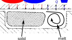
Calculation of convection in the melt vortex
The calculation of convection in the melt vortex (SW) is based on the assumption of a plane wall with longitudinal flow around it. This results in the following dimensionless key figures:
$$\text{The Reynolds number } Re=\frac{L_{char} \cdot \rho \cdot v_0}{\eta}$$ $$\text{The Prandtl number } Pr = \frac{\eta \cdot c_p}{\lambda}$$ $$\text{The Nusselt number } Nu = 0.6774 \cdot \sqrt{Re} \cdot Pr^{1/3}$$
with the characteristic length $L_{char}$, which corresponds to the channel height, the density $\rho$, the circumferential speed $v_0$, the viscosity $\eta$, the heat capacity $c_p$ and the thermal conductivity $\lambda$. The heat transfer coefficient $\alpha$ can also be calculated from the Nusselt number:
$$\alpha = \frac{Nu \cdot \lambda}{L_{char}}$$
The heat flow results from the heat flow density $\dot q$, the temperature difference between the melt and the cylinder $\Delta T$ and the area of the heat transfer $A = b \cdot (1-y) \cdot Z$ with the channel width $b$, the solid bed width $y$ and the channel length $Z$
$$\dot q_{SW} = \alpha \cdot \Delta T$$ $$\dot Q_{SW} =\dot q_{SW} \cdot A$$
Calculation of heat conduction via the melt film
The calculation of the heat flux density by heat conduction in the melt film (SF) is derived from the analytically calculated temperature profile in the melt film. The temperature gradient on the cylinder is used for this:
$$\dot q_{SF} = \frac{dT}{d \xi} \Bigg \vert_{\xi=1} \cdot \frac{\lambda}{\overline \delta}$$ $$\dot q_{SF} = (T_Z-T_{Fl}) \left\{ 1 + Br_{SW} \left[ \frac{exp \left[ - \beta (T-T_{Fl}) \right] \cdot \left[ (1-A)e^A - 1 \right]}{A^2} \left( \frac{A}{e^A-1} \right)^{1+n} \right] \right\} \cdot \frac{\lambda}{\overline \delta}$$ $$\text{with}$$ $$A = \frac{\beta}{n} (T_Z-T_{Fl})$$ $$\text{and}$$ $$Br_{SW} = \frac{K \cdot v_{rel}^{1+n} \cdot \bar{\delta}^{1-n}}{\lambda (T_Z - T_{Fl})}$$
with the thermal conductivity $\lambda$, the mean melt film thickness $\overline \delta$, the cylinder temperature $T_Z$, the flow temperature (melting temperature) $T_{Fl}$, the temperature in the melt vortex $T$, the Brinkmann number in the melt film $Br_{SW}$, the temperature coefficient in the flow law $\beta$, the flow law exponent $n$, the consistency factor $K$ and the relative velocity between cylinder and solid bed $v_{rel}$.
The heat flow is also calculated from the heat flow density by multiplying it by the area of the solid bed:
$$\dot Q_{SF} = \dot q_{SF} \cdot b \cdot y \cdot Z$$
with the channel width $b$, the solid bed width $y$ and the channel length $Z$.