Dies ist eine alte Version des Dokuments!
Grooved bush
Calculation options
The throughput behaviour of grooved bushes can be calculated with 2 settings:
- Stiff (standard)
- Speed limit orientated
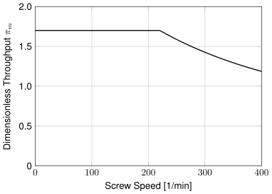
In the rigid conveyor calculation, the throughput is directly proportional to the screw speed.
In the limit speed-oriented calculation, a limit speed is calculated from which the solid friction in the grooved bushing changes to melt film friction. This reduces the specific throughput. Additional material data (friction coefficient at the transition from solid friction to melt film friction) is required. As the model reacts sensitively to friction values and the problem of melt film formation in grooved bushings is only of minor significance due to the available empirical values in grooved bushing design, the limit speed-orientated calculation is not the standard model.
Case differentiation
In addition to the option of automatic case differentiation, the user can specify which conveyor mechanism is to be selected for the calculation.
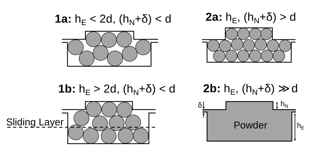
If automatic case differentiation is activated, the support situations are differentiated as follows:
- Case 1a: The pellet diameter is greater than the groove depth (incl. screw clearance) and the channel is shallower than twice the pellet diameter; the maximum possible conveying effect prevails due to the wedging of the pellets in the entire channel (positive conveying), i.e. the maximum throughput is also achieved in this case.
- Case 1b: The pellet diameter is greater than the groove depth (incl. screw clearance), but the channel is deeper than twice the pellet diameter; there is an interaction between the groove and channel conveying, and the maximum possible conveying effect is only present in the upper area of the channel.
- Case 2a: The pellet diameter is smaller than the groove depth (incl. screw clearance), there is frictional flow over the entire channel depth; there is no conveying in the grooves themselves. In addition to the purely analytical calculation of conveying case 2a, it is also possible to carry out a numerically corrected calculation. In this case, the analytically determined conveying angle is multiplied by a correction factor based on extensive numerical simulations using the Discrete Element Method (DEM). The following parameters were varied in these simulations: Pellet diameter, friction coefficients, barrel diameter, flight depth, flight pitch, groove angle, screw peripheral speed and back pressure at the end of the grooved bush. For conveying case 2a, the flight depth, flight pitch, groove angle and circumferential speed have proven to be particularly relevant influencing factors on the correction factor and have therefore been implemented. In the varied practice-relevant areas of the test plan, it was found that the conventional analytical calculation predominantly overestimates the throughput because the assumed block flow cannot always be maintained in the DEM simulations. Instead, there is partial sliding of granulate layers, which is taken into account by the ‘numerically corrected’ option.
- Case 2b: The pellet diameter is much smaller than the groove depth (incl. screw clearance); there is frictional flow over the entire channel depth, whereby there is no conveying in the grooves themselves and a calculation is only possible empirically
Source
- Brüning, Florian: Modellierung der Feststoffförderung im Einzug von Nutbuchsenextrudern mit Hilfe von DEM-Simulationen, Dissertation, Universität Paderborn, 2023