Dies ist eine alte Version des Dokuments!
Barrier section
General geometry of a barrier section
Barrier zones are much more complex in their structure than feed, (de)compression and metering zones. In a barrier section, a distinction is made between solid and melt channel, as can be seen in the following illustrations.


While the main flight comes from the previous section and merges into the subsequent zone, there is a barrier flight within the barrier section that separates the solids channel from the melt channel.
At the beginning of the barrier zone, the solids channel predominates, whereas the melt channel begins anew. In the course of the barrier zone, the channel cross-section of the solids channel usually becomes smaller and that of the melt channel usually becomes larger. Typically, the solids channel is kept as wide and flat as possible so that the highest possible melting rate is achieved due to the large surface area. By reducing the channel cross-section, the melted plastic passes into the melt channel, which typically has a high channel depth for good temperature control.
At the end of the barrier zone, the solids channel runs out and the melt channel predominates. Both the inlet and outlet can be selected to be closed (see figure above) or open.
In order to fully define a barrier screw, the information shown in the following schematic diagram is required.

| Input identifier | Description |
|---|---|
| L or L/D | Length of the zone |
| δ (delta) | Screw clearance |
| b_i | Number of channel pairs |
| t_h or t_h/D | Pitch of main section |
| t_b or t_b/D | Pitch of barrier section |
| e_h | Flight width of main section |
| e_b | Flight width of barrier section |
| s_0 and s_1 | Barrier gap at the start and end of the current zone |
| b_s_0 | Channel width of the melt channel (can only be entered at the start of the inlet) |
| h_f_0 and h_f_1 | Channel depth of the solids channel at the start and end of the current zone |
| h_s_0 and h_s_1 | Channel depth of the melt channel at the start and end of the current zone |
| r_f_tr | Radius active flight of main flight |
| r_f_ntr | Radius non active flight of main flight |
| r_s_tr | Radius active flight of barrier flight |
| r_s_ntr | Radius non active flight of barrier flight |
| gamma_f | Flight angle of main flight |
| gamma_s | Flight angle of barrier flight |
It should be noted that a barrier zone always consists of an inlet, at least one main section and an outlet. Several main zones can be defined in succession in order to make gradual changes to the channel geometry. These can be added or removed using the „+“ and „-“ in the top right-hand corner of the input window. The number of pairs can only be changed in the inlet zone. The other barrier zones adopt these values.
Notes
IMPORTANT: In REX/PSI, the barrier zone inlet does not begin where the barrier flight emerges from the main flight, but only at the position where the melt channel begins. An initial melt channel width b_s_0 (> 0 mm) must be specified at the start of a barrier inlet zone. For example, if the melt channel starts with a radius of 2 mm between the barrier and main flight, the initial channel width of the melt channel is assumed to be 4 mm and the start of the barrier zone is also set to this position.
The division into the individual barrier zones is usually determined on the basis of changes in the flight pitch or changes in the channel depth profile.

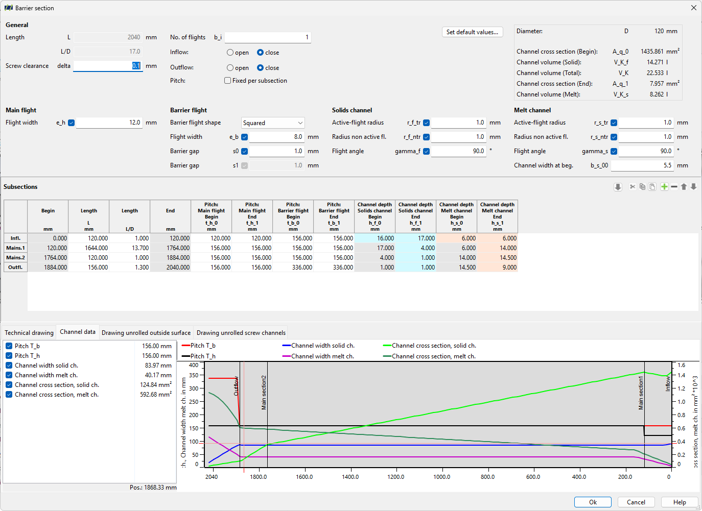
Input mask
Overview of input masks
Classic dialogue
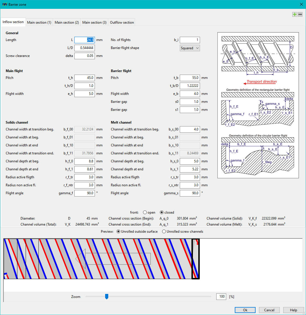
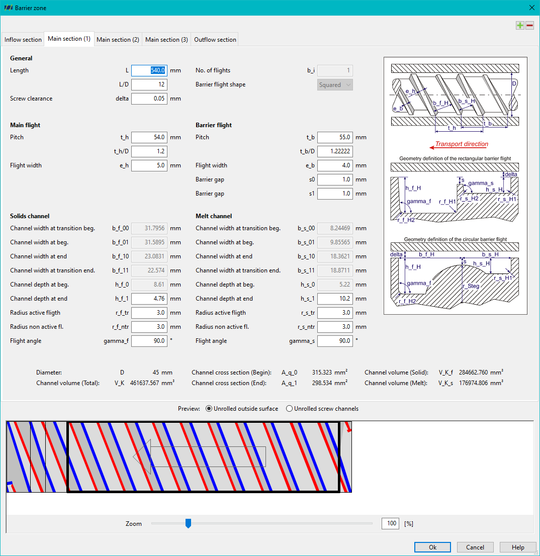
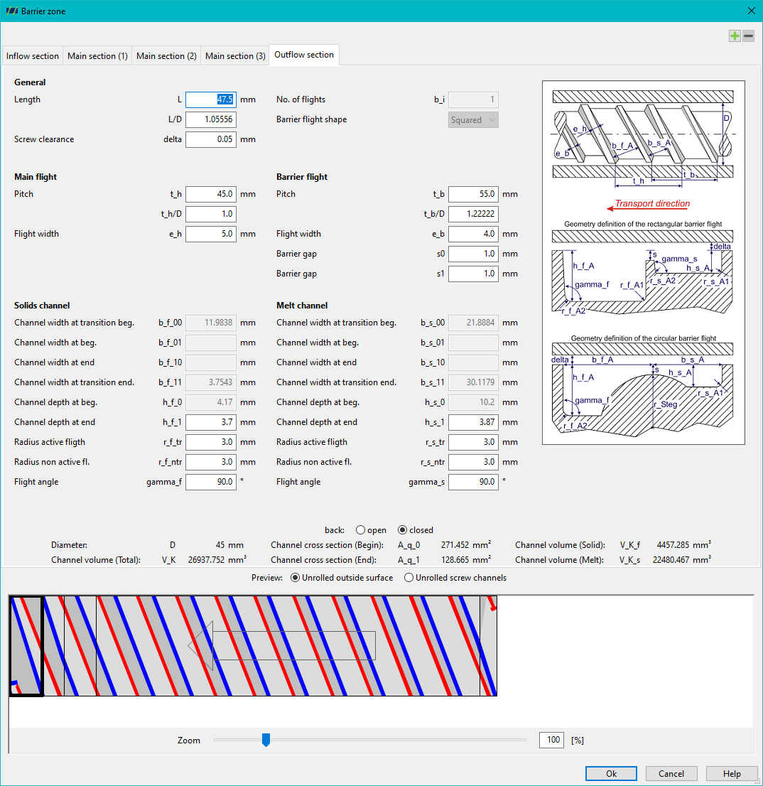
New dialogue
Determination of channel widths
The calculation of the channel widths within the barrier inflow-, main- and outflow section has been revised in REX version 6 and 18 respectively PSI version 4 and 16. Therefore, the saved values of a barrier screw file in a previous PSI/REX version will generally not correspond to the channel widths of a newly entered barrier screw although the geometrical parameters that determine the channel width (length, gear pitch, etc.) are identical.
When loading a barrier screw file from an earlier REX/PSI version, REX or PSI automatically updates the stored solid and melt channel widths. If the user performs a calculation with the previously loaded barrier screw, the calculation will be carried out using the updated channel widths.
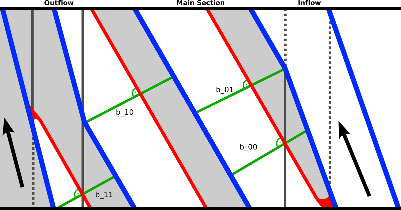
The barrier zone begins with the barrier flight and ends with the barrier flight. The position for determining the channel width is therefore on the barrier flight. The position where the barrier flight begins (in REX/PSI, i.e. where the initial width of the melt channel is specified) determines the initial channel widths of the barrier zone (coordinate x=0 in the following figure).

This means that the passive (non-driving) side of the barrier flight determines the position for determining the channel width as a function of the coordinate x in the axial direction. However, as can be seen in the figure, the channel width is always determined orthogonal to the main flight.
In the inflow and outflow section, only the channel widths at the zone transition (b_f/s_00 and b_f/s_11) are specified. In barrier main sections, the widths are also specified at the positions at which the channels are first (b_f/s_01) and last (b_f/s_10) completely within the main section (see following figure).