Dies ist eine alte Version des Dokuments!
Define screw data
The following window opens when you create a slug:
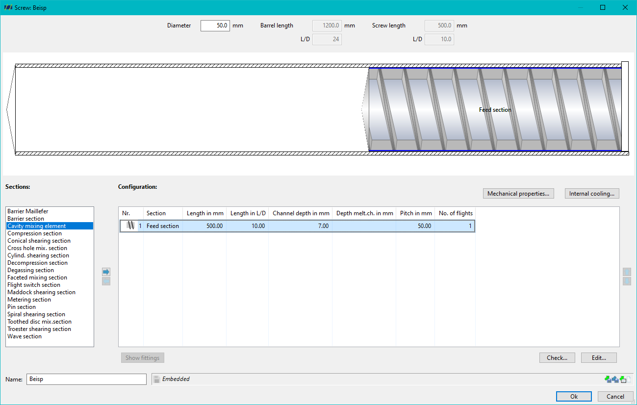
The extruder diameter (nominal diameter / diameter of the barrel) can be entered or changed in the upper area. The greyed out fields are only used to display the ACTUAL screw geometry.
Below the graphic representation of the screw, there are two buttons for further optional configuration:
- Input of the mechanical properties (see also Strength calculation)
- Input of an internal temperature control
The screw can be defined in the centre of the window. The screw always starts automatically (and must) with a feed zone. All possible zones are listed in the left-hand area. These can be added to the current screw configuration by double-clicking or by selecting and pressing the arrows (Insert section ). The order of the screw zones can be adjusted using the arrows on the right (move section forwards
  / backwards
  ). The required zone data can be entered by double-clicking on the list entry in the current screw configuration or by pressing the Edit button.
If REX has automatically made adjustments to zones (e.g. if the channel depth of a compression section is changed, the channel depths of the adjacent sections are automatically adjusted), the overview of all automated changes can be viewed using the Show adjustments button.
The Check button performs a manual check of the validity of the screw geometry. The screw geometry is also checked automatically each time a change is made.
At the bottom of the window, the current screw configuration can be imported from a file, saved, transferred from another process or reset. If Embedded appears at the bottom of the display field, this means that the current screw configuration is saved in the associated process file.