Dies ist eine alte Version des Dokuments!
Feed, Metering and Venting section

The input mask for sections with constant flight depth is identical for the feed section, the metering section and the venting section. The differentiation has only been made to specify the screw sections exactly and to set the diameter in the feed section. The geometrical parameters to be entered from the basis of the calculation algorithms are implemented in the program and must be defined completely.
The following illustration shows the geometry of a single flight screw section.

| Input identifier | Description |
|---|---|
| L or L/D | Length of the zone |
| δ (delta) | Screw clearance |
| i | No. of flights |
| r_1 | Radius active flight |
| r_2 | Radius non active flight |
| γ (gamma) | Flight angle |
| e | Flight width |
| t or t/D | Pitch |
| h_E, h_M, h_0 | Channel depth (E: Intake, Metering, 0: Degassing) |
The corresponding input screen (feed zone) with the required sizes is shown below:
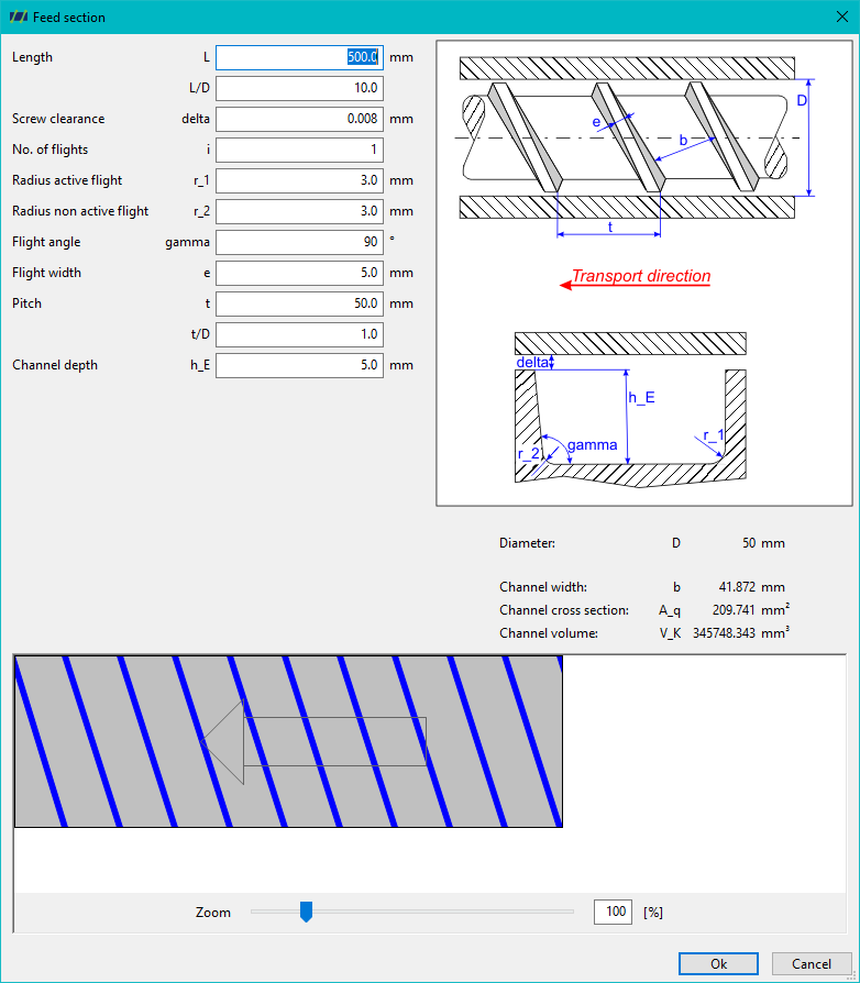
Once all input variables have been defined, the following variables are calculated automatically:
| Calculated identifier | Description |
|---|---|
| b | Channel width |
| A_q | Channel cross section |
| V_K | Channel volume |
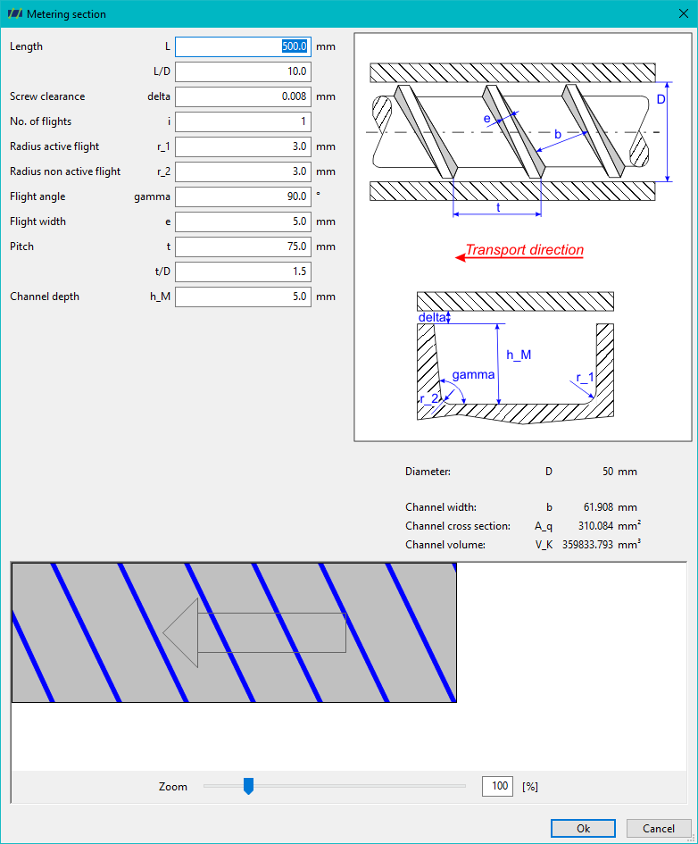
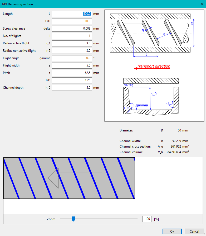
The dialogues of the metering and degassing zones differ only in the illustration and the designation of the aisle depth h_0 (degassing zone), h_M (metering zone).