Dies ist eine alte Version des Dokuments!
General notes on defining the screw geometry
The following paragraphs serve for the specification of the geometrical values, which are needed in the input mask.
Input of values
Fields with a grey background cannot be edited because they are either dependent on other variables and are therefore determined by REX/PSI (e.g. the channel width) or are defined by the input in previous screw zones (e.g. the diameter).
Some values, such as the length $L$ or the pitch $t$, can be specified either as absolute values or as dimensionless values in relation to the diameter $D$.
As the leakage current is taken into account in the calculations, the following definitions must be observed:
- The inner cylinder diameter (the ‘nominal diameter’) must be entered as the diameter $D$. This can only be set in the feed zone.
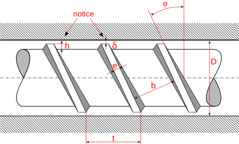
- The screw clearance $δ$ (delta) describes the radial clearance between the screw and the barrel.
- All other geometry variables of the screw are independent of the barrel diameter.
- A distinction is made between the worm clearance $δ$ (delta) and the flight depth $h$.
The only exceptions here are the cylindrical and the conical shear part. For these two shear sections, the shear gap height from the base of the shear section to the cylinder surface must be entered.
Notes on radii, flank angle and channel width
In the individual screw zones, radii can be specified on the driving ($r_1$) and non-driving ($r_2$) flank of the screw channel as well as a flank angle of the non-driving flank. The driving flank, also known as the active flank, represents the side of the screw flight that pushes the plastic towards the screw tip due to the screw rotation. The non-driving flank, also known as the passive flank, is therefore the other side of the screw flight.
The following figure shows three examples for entering the radii and the flank angle.

Basically, the width of the channel results in
$$b=t \cdot cos(\varphi) - e$$
$$\text{with}$$
$$tan(\varphi)=\frac{t}{\pi \cdot (D-h)}$$
with the pitch $t$, the pitch angle $\varphi$, the flight width $e$ and the nominal screw diameter $D$.
In the figure above, however, areas that reduce the channel cross-section are marked in red. As REX/PSI always calculates with a simplified rectangular duct, the reduction of the duct cross-section is taken into account by a reduced duct width:
$$b_{effective}=\frac{b \cdot h-A_{radii,\gamma}}{h}$$
Dividing the actual duct cross-section by the duct height $h$ results in the effective duct width.
The duct cross-section $A_{radii,\gamma}$ is calculated as follows: $$A_{r<h,\gamma=90°} = \frac{r^2}{4} (4 - \pi)$$
$$ A_{r<h,\gamma>90°} = r^2 \left( \frac{1 + \cos \gamma}{\sin \gamma} - \pi \frac{180^\circ - \gamma}{360^\circ} \right) - \frac{1}{2} \frac{h^2}{\tan \gamma} $$
$$ A_{r>h,\gamma=90°} = \frac{1}{2}(r + h) r \sin \left[ \arccos\left(1 - \frac{h}{r}\right) \right] - \frac{\pi r^2}{360^\circ} \arccos\left(1 - \frac{h}{r}\right) $$
Notes on calculating the duct cross-section and volume
The calculation of the duct cross-section takes into account the actual duct width $b$, the effective duct width $b_{effective}$, the duct height $h$, the web width $e$ and the screw clearance $\delta$. The channel volume is made up of 2 areas:
$$A_{ges.}=A_{Kanal}+A_\delta$$ $$\text{with}$$ $$A_{channel} = b_{effective} \cdot h$$ $$\text{and}$$ $$A_\delta = \delta \cdot (b+e)$$
The duct volume is calculated by multiplying the duct cross-section by the unwound duct length $L_{duct}$:
$$V_{channel} = A_{ges} \cdot L_{channel}$$ $$\text{with}$$ $$L_{channel} = \frac{L_{zone}}{sin(\varphi)}$$
with the pitch angle $\varphi$