Dies ist eine alte Version des Dokuments!
Definition of a Die geometry (REX)
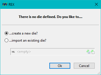
In REX Next Generation, you have the option to define specific die elements in order to calculate key process parameters such as the pressure at the screw tip. This function is particularly relevant for the precise simulation and optimization of polymer processing operations, as the geometry of the die elements has a direct influence on the back pressure and, consequently, on the throughput.
Available tool elements
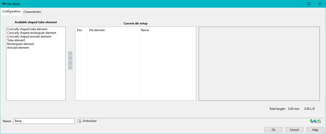
REX Next Generation provides you with a range of predefined tool elements that can be used in the simulation. These tool elements cover the most common cross-section shapes used in practice. The following elements are available:
- Conically shaped tube element: This element describes a circular cross-section whose diameter varies over its length.
- Conically shaped rectangular element: A rectangular cross-section whose width and/or height varies along the length of the die.
- Conically shaped annular element: An annular gap with tapered diameters.
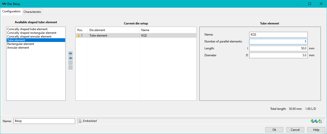
- Tube element: A simple circular cross-section with a constant diameter.
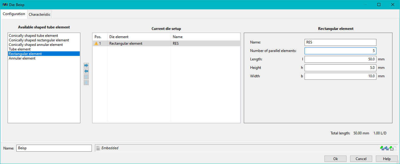
- Rectangular element: A constant rectangular cross-section.
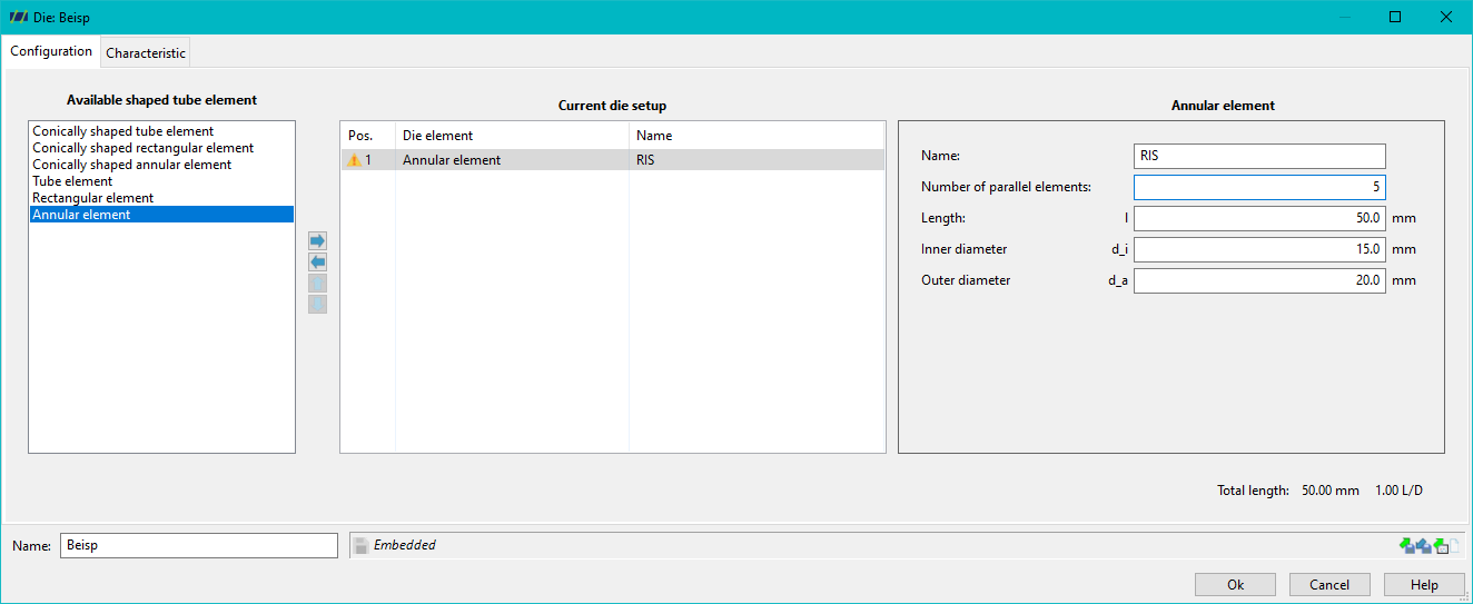
- Annular element: An annular gap with constant diameters.
Definition of geometry sizes
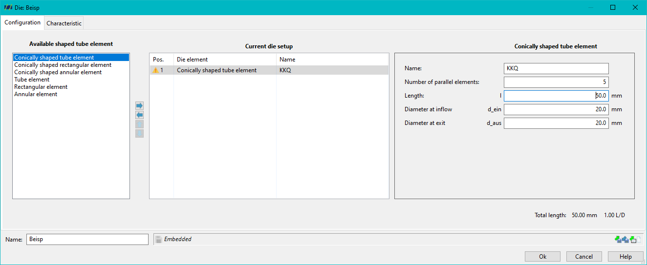
You can define specific geometry sizes for each of these mould elements. These variables are crucial for the precise simulation of the material flow and the pressure conditions within the mould. The common geometry parameters that you can define include:
- Diameter (for circular cross-sections)
- Width and height (for rectangular cross-sections)
- Gap height (for annular gaps)
- Length of the elements
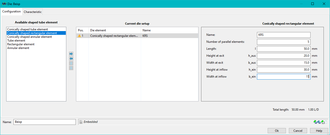
By entering these parameters, you can ensure that the simulation accurately reflects the actual physical properties of the die, which leads to realistic results.
Naming and number of parallel elements
In addition to the geometry, you can name each tool element individually to better organise and identify the different components within the process. This is particularly helpful when several tool elements are used in a process.
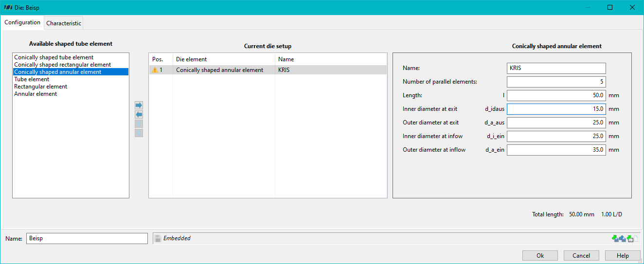
Another important feature is the ability to specify the number of elements connected in parallel. This makes it possible to use several identical mould elements in parallel in a process in order to simulate the material flow through several channels simultaneously. This function is particularly useful for processes with multi-channel or multi-strand extrusion.
Arrangement of the tool elements
To enable a precise visualisation of the entire tool, you can flexibly arrange the tool elements. The right arrow, left arrow, up and down buttons are available for this purpose. You can use these buttons to
- Add new tool elements: You can add further elements to the list in order to design the structure of the tool in detail.
- Move elements: If you want to change the order of the elements, you can use the arrow buttons to move them to the desired position. This is particularly useful to ensure that the tool elements are used in the correct order in the simulation.
Importance of the tool elements for the simulation
The precise definition and arrangement of the mould elements is crucial for the quality of the simulation results. By taking into account the various geometries and their influence on the material flow, you can perform precise calculations, such as the pressure at the screw tip or the speed of the material outlet. These parameters are of great importance in plastics technology, as they have a direct influence on the quality of the end product.