Dies ist eine alte Version des Dokuments!
Screw
General screw presentation
The screw drawing provides you with a comprehensive overview of your machine’s configuration. In the upper left tab under ‘General’, you will find the essential process data, such as the project path, the process name, the responsible operator, and any comments that may have been added. This information allows for quick orientation and precise documentation of the current project.
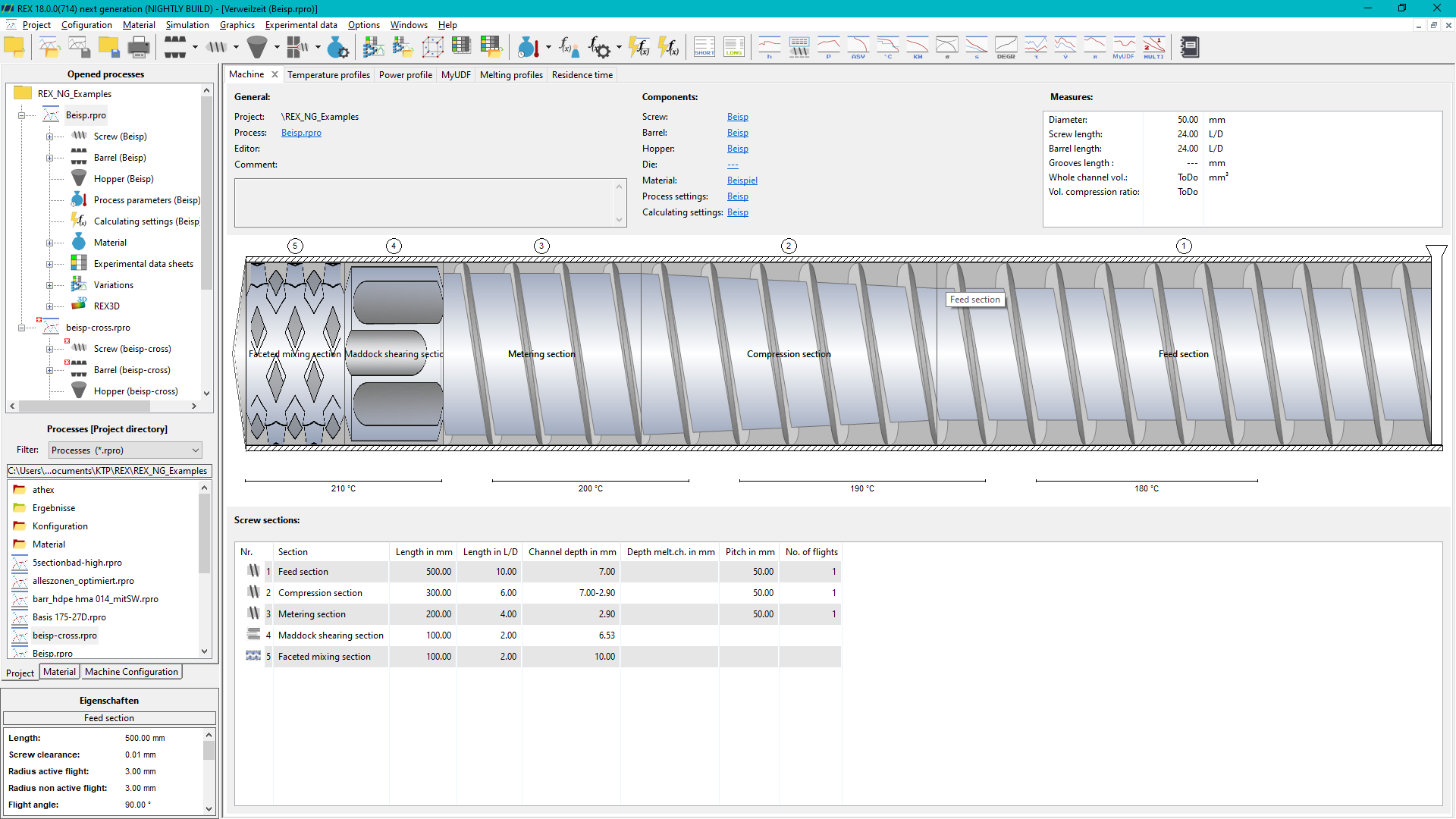 In the ‘Components’ section, all machine-relevant components that are significant for the process are listed. This includes the screw configuration, the cylinder configuration, the definition of hopper data, the definition of a tool if applicable, the determination of the material to be processed, the specification of process parameters, and the calculation settings. This detailed listing provides you with a precise overview of the key machine settings and process parameters.
Additionally, significant machine dimensions are specified. These include, among others, the screw diameter, the screw length, the housing length, and, in the case of grooved barrel extruders, the groove length, the total channel volume of the machine, and the compression ratio. These dimensions are crucial for understanding and optimizing the extrusion process.
The main part of the representation visualizes the screw itself, complemented by the cylinder temperatures along the screw. This graphical representation provides a clear overview of the thermal conditions and the screw geometry.
Below the screw drawing, the individual screw zones are detailed in a list format. For each zone, the respective lengths, channel depths, and pitch angles are specified. This precise breakdown of the screw zones enables detailed analysis and optimization of the extrusion parameters.
Overall, the screw drawing offers a detailed and at the same time clear presentation of the relevant machine configurations, providing a solid basis for the analysis and optimization of the extrusion process.
Illustration of the channel geometry
The screw geometry is shown in more detail in the diagram ‘channel geometry’ (diagram with ‘h’ symbol). The channel depth, channel width and channel cross-section over the screw length are shown here.