Dies ist eine alte Version des Dokuments!
Post-Processing
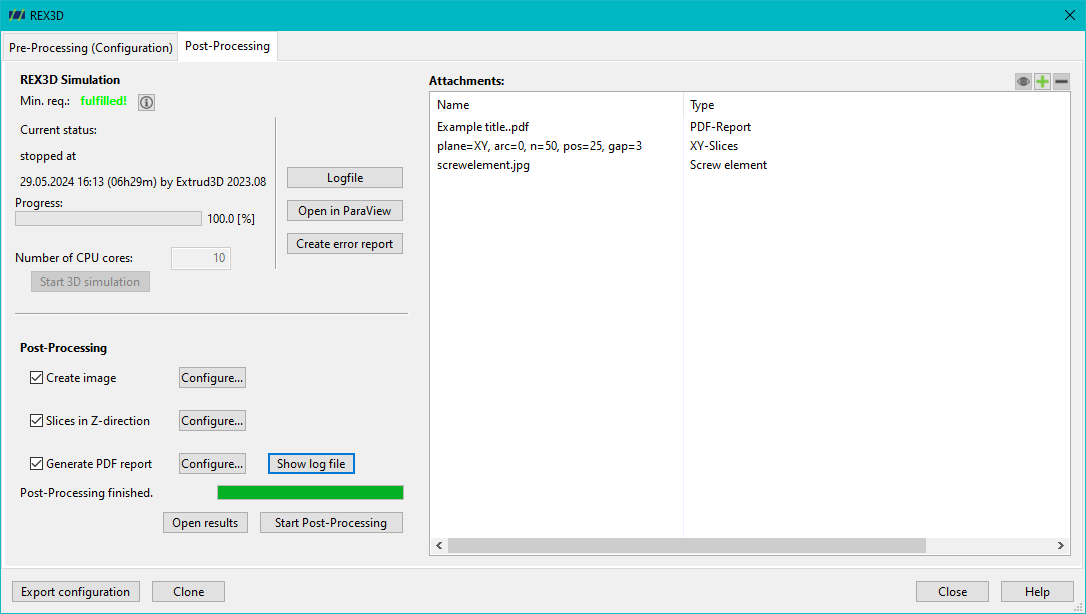
After a simulation has been successfully completed, various post-processing steps can be carried out:
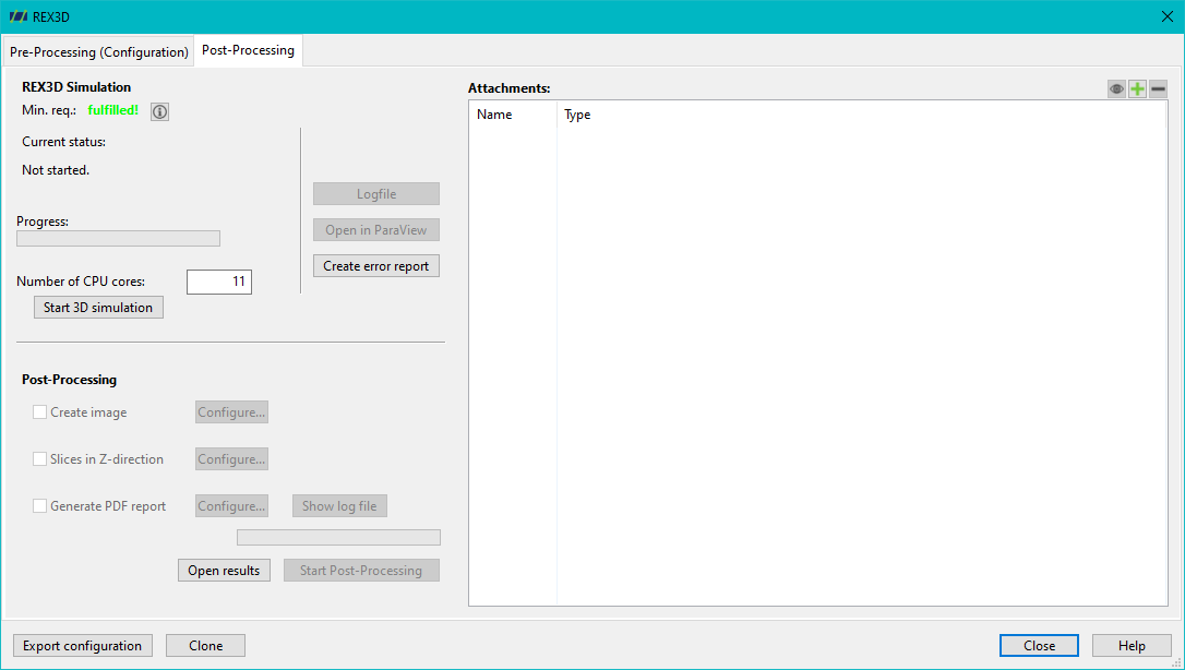
There are various configuration options for the individual post-processing steps:
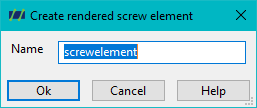
Create image file
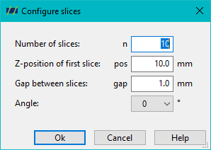
Cutting planes in the Z direction
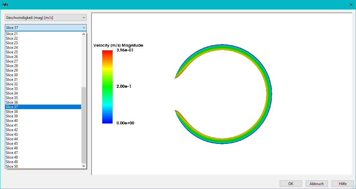
For cutting planes in the Z direction, it is possible to select the number of cutting planes, the Z position of the first cutting plane and the distance between the cutting planes. If several time planes have been simulated, the time plane or screw position to be analysed can be determined via the angle. If only one time plane has been simulated, only one angular position is available for selection.
PDF Generate report
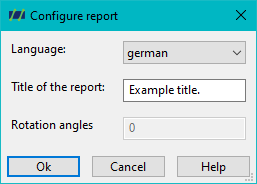
In post-processing, it is also possible to generate a PDF report containing a general evaluation of the flow simulation. Before the PDF report is created, it is possible to define the language and title of the report. define the language and title of the report.
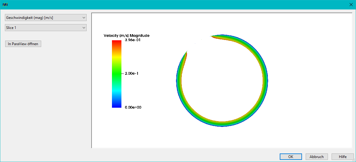
Once the various post-processing functions have been carried out, their results can be called up in the Attachments field. An example of this is the following figure, which shows the flow velocity on an XY section plane.
Display results in the attachments
The Display results of a numerical 3D simulation button or the control path: Simulation > REX3D Open diagram takes you to the storage location of the files already created.
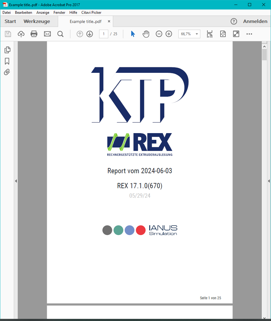
PDF report
The PDF report clearly summarises the numerical results.
Cutting planes in Z direction
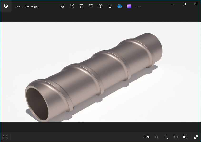
Rendered screw element